Thingsboard is an open-source server-side platform that allows you to monitor and control IoT devices.
It is free for both personal and commercial usage and you can deploy it anywhere.
If this is your first experience with the platform we recommend to review
what-is-thingsboard page and getting-started guide.
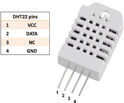
This sample application performs collection of temperature and humidity values produced by DHT22 sensor and further visualization on the real-time web dashboard.
Collected data is pushed via MQTT to Thingsboard server for storage and visualization.
The purpose of this application is to demonstrate Thingsboard data collection API and visualization capabilities.
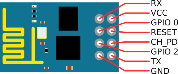
The DHT22 sensor is connected to ESP8266.
ESP8266 offers a complete and self-contained Wi-Fi networking solution.
ESP8266 push data to Thingsboard server via MQTT protocol by using PubSubClient library for Arduino.
Data is visualized using built-in customizable dashboard.
The application that is running on ESP8266 is written using Arduino SDK which is quite simple and easy to understand.
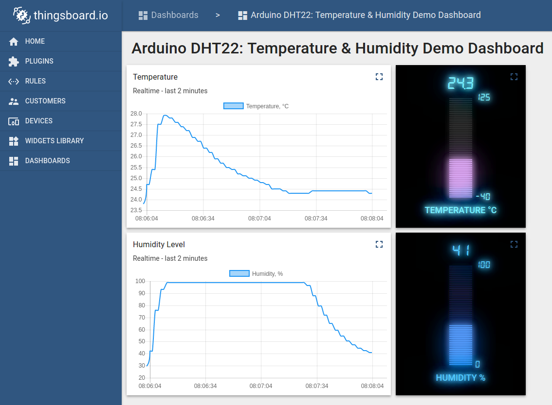
The video below demonstrates the final result of this tutorial.
Once you complete this sample/tutorial, you will see your sensor data on the following dashboard.
Prerequisites
You will need to Thingsboard server up and running. Use either Live Demo or
Installation Guide to install Thingsboard.
List of hardware and pinouts
-
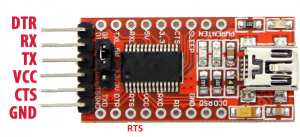
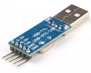
USB to TTL
-
Resistor (between 4.7K and 10K)
-
Breadboard
-
2 female-to-female jumper wires
-
10 female-to-male jumper wires
-
3 male-to-male jumper wire
-
3.3V power source (for example 2 AA batteries)
Wiring schemes
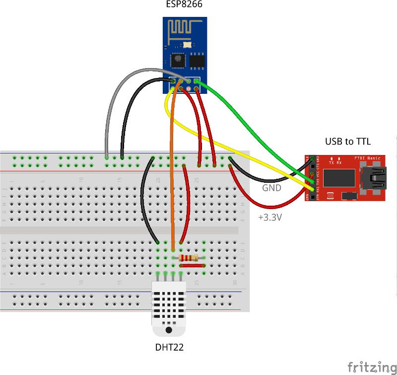
Programming/flashing schema
| ESP8266 Pin |
USB-TTL Pin |
| ESP8266 VCC |
USB-TTL VCC +3.3V |
| ESP8266 CH_PD |
USB-TTL VCC +3.3V |
| ESP8266 GND (-) |
USB-TTL GND |
| ESP8266 GPIO 0 |
USB-TTL GND |
| ESP8266 RX |
USB-TTL TX |
| ESP8266 TX |
USB-TTL RX |
| DHT-22 Pin |
ESP8266 Pin |
| DHT-22 Data |
ESP8266 GPIO 2 |
| DHT-22 Pin |
USB-TTL Pin |
| DHT-22 VCC |
USB-TTL VCC +3.3V |
| DHT-22 GND (-) |
USB-TTL GND |
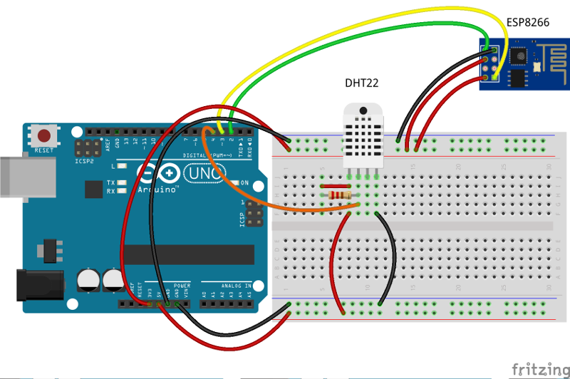
Finally, place a resistor (between 4.7K and 10K) between pin number 1 and 2 of the DHT sensor.
The following picture summarizes the connections for this project in programming/debug mode:
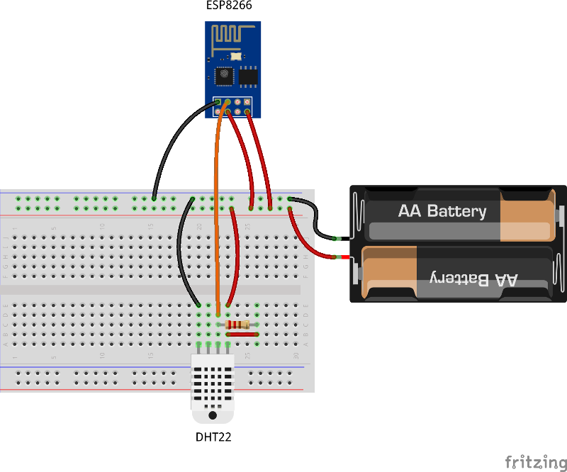
Final schema (Battery Powered)
| ESP8266 Pin |
3.3V power source |
| ESP8266 VCC |
VCC+ |
| ESP8266 CH_PD |
VCC+ |
| ESP8266 GND (-) |
VCC- |
| DHT-22 Pin |
ESP8266 Pin |
| DHT-22 Data |
ESP8266 GPIO 2 |
| DHT-22 Pin |
3.3V power source |
| DHT-22 VCC |
VCC+ |
| DHT-22 GND (-) |
VCC- |
The final picture:
Thingsboard configuration
Note Thingsboard configuration steps are necessary only in case of local Thingsboard installation.
If you are using Live Demo instance all entities are pre-configured for your demo account.
However, we recommend to review this steps because you will still need to get device access token to send requests to Thingsboard.
Provision your device
This step contains instructions that are necessary to connect your device to Thingsboard.
Open Thingsboard Web UI (http://localhost:8080) in browser and login as tenant administrator
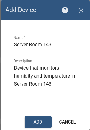
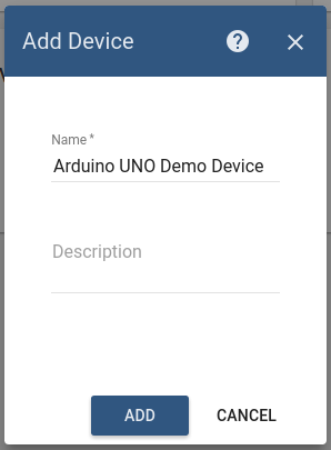
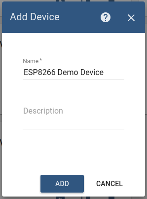
Goto “Devices” section. Click “+” button and create device with name “ESP8266 Demo Device”.
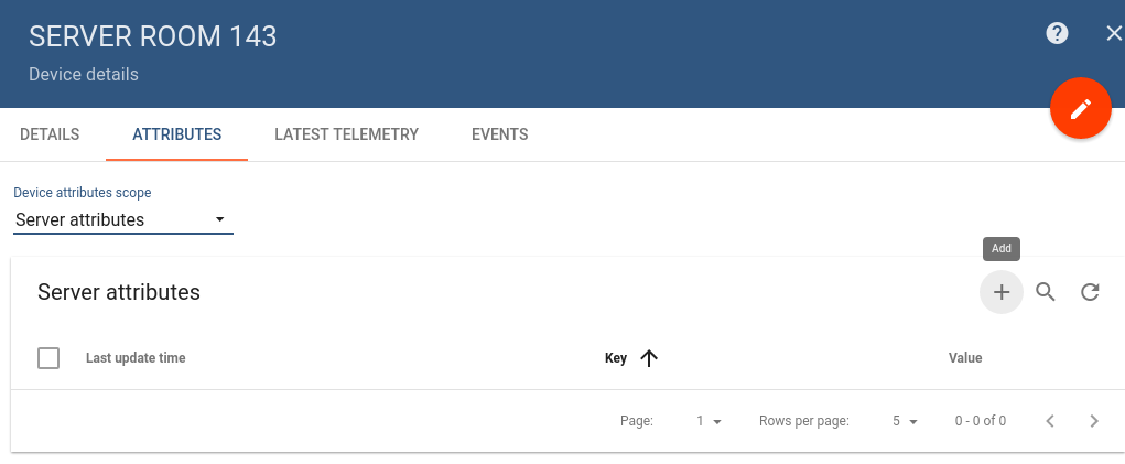
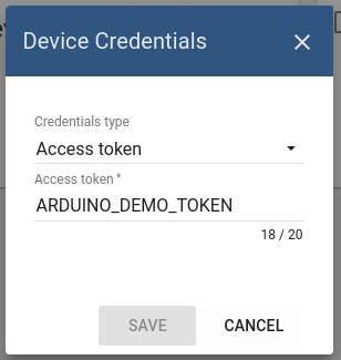
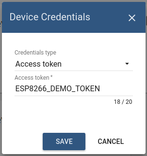
Once device created, open its details and click “Manage credentials”.
Copy auto-generated access token from the “Access token” field. Please save this device token. It will be referred to later as $ACCESS_TOKEN.
Click “Copy Device ID” in device details to copy your device id to clipboard.
Paste your device id to some place, this value will be used in further steps.
Provision your dashboard
This step contains instructions that are necessary to provision new dashboard with map widgets to Thingsboard.
Open “Terminal” and download file containing demo dashboard JSON:
curl -L https://thingsboard.io/docs/samples/esp8266/resources/esp8266_dht_temp_dashboard.json > esp8266_dht_temp_dashboard.json
Update dashboard configuration with your device Id (obtained in previous step) by issuing the following command:
sed -i "s/{DEVICE_ID}/<your device id>/" esp8266_dht_temp_dashboard.json
Obtain JWT token by issuing login POST command:
curl -X POST --header 'Content-Type: application/json' --header 'Accept: application/json' -d '{"username":"[email protected]", "password":"tenant"}' 'http://localhost:8080/api/auth/login'
You will receive response in the following format:
{"token":"$YOUR_JSON_TOKEN", "refreshToken": "$REFRESH_TOKEN"}
copy $YOUR_JSON_TOKEN to some place. Note that it will be valid for 15 minutes by default.
Execute dashboard upload command:
curl -X POST --header 'Content-Type: application/json' --header 'Accept: application/json' --header 'X-Authorization: Bearer $YOUR_JSON_TOKEN' -d "@esp8266_dht_temp_dashboard.json" 'http://localhost:8080/api/dashboard'
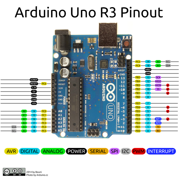
Programming the ESP8266
Step 1. ESP8266 and Arduino IDE setup.
In order to start programming ESP8266 device you will need Arduino IDE installed and all related software.
Download and install Arduino IDE.
After starting arduino, open from the ‘file’ menu the preferences.
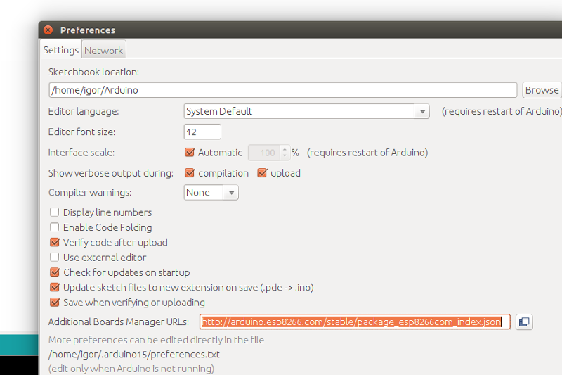
Fill in the “Additional board managers URL” this url: http://arduino.esp8266.com/stable/package_esp8266com_index.json
Close the screen by the OK button.
Now we can add the board ESP8266 using the board manager.
Click in the menu tools the menu option Board: “Most likely Arduino UNO”.
There you will find the first option “Board Manager”.
Type in the search bar the 3 letters ESP. Locate and click on “esp8266 by ESP8266 Community”.
Click on install and wait for a minute to download the board.
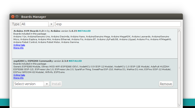
Note that this tutorial was tested with the “esp8266 by ESP8266 Community” version 2.3.0.
In the menu Tools “Board “Most likely Arduino UNO” three new boards are added.
Select “Generic ESP8266 Module”.
Prepare your hardware according to the Programming/flashing schema.
Connect USB-TTL adapter with PC.
Select in the menu Tools, port the corresponding port of the USB-TTL adapter.
Open the serial monitor (by pressing CTRL-Shift-M or from the menu Tools).
Set the key emulation to “Both NL & CR” and the speed to 115200 baud. This can be set in the bottom of terminal screen.
Step 2. Install Arduino libraries.
Open Arduino IDE and go to Sketch -> Include Library -> Manage Libraries.
Find and install the following libraries:
Note that this tutorial was tested with the following versions of the libraries:
- PubSubClient 2.6
- Adafruit Unified Sensor 1.0.2
- DHT sensor library 1.3.0
Step 3. Prepare and upload sketch.
Download and open esp8266-dht-mqtt.ino sketch.
Note You need to edit following constants and variables in the sketch:
- WIFI_AP - name of your access point
- WIFI_PASSWORD - access point password
- TOKEN - the $ACCESS_TOKEN from Thingsboard configuration step.
- thingsboardServer - Thingsboard HOST/IP address that is accessable within your wifi network. Specify “demo.thingsboard.io” if you are using live demo server.
resources/esp8266-dht-mqtt.ino |
|---|
#include "DHT.h"
#include <PubSubClient.h>
#include <ESP8266WiFi.h>

#define WIFI_AP "YOUR_WIFI_AP"
#define WIFI_PASSWORD "YOUR_WIFI_PASSWORD"

#define TOKEN "ESP8266_DEMO_TOKEN"

// DHT
#define DHTPIN 2
#define DHTTYPE DHT22

char thingsboardServer[] = "YOUR_THINGSBOARD_HOST_OR_IP";

WiFiClient wifiClient;

// Initialize DHT sensor.
DHT dht(DHTPIN, DHTTYPE);

PubSubClient client(wifiClient);

int status = WL_IDLE_STATUS;
unsigned long lastSend;

void setup()
{
  Serial.begin(115200);
  dht.begin();
  delay(10);
  InitWiFi();
  client.setServer( thingsboardServer, 1883 );
  lastSend = 0;
}

void loop()
{
  if ( !client.connected() ) {
    reconnect();
  }

  if ( millis() - lastSend > 1000 ) { // Update and send only after 1 seconds
    getAndSendTemperatureAndHumidityData();
    lastSend = millis();
  }

  client.loop();
}

void getAndSendTemperatureAndHumidityData()
{
  Serial.println("Collecting temperature data.");

  // Reading temperature or humidity takes about 250 milliseconds!
  float h = dht.readHumidity();
  // Read temperature as Celsius (the default)
  float t = dht.readTemperature();

  // Check if any reads failed and exit early (to try again).
  if (isnan(h) || isnan(t)) {
    Serial.println("Failed to read from DHT sensor!");
    return;
  }

  Serial.print("Humidity: ");
  Serial.print(h);
  Serial.print(" %\t");
  Serial.print("Temperature: ");
  Serial.print(t);
  Serial.print(" *C ");

  String temperature = String(t);
  String humidity = String(h);


  // Just debug messages
  Serial.print( "Sending temperature and humidity : [" );
  Serial.print( temperature ); Serial.print( "," );
  Serial.print( humidity );
  Serial.print( "]   -> " );

  // Prepare a JSON payload string
  String payload = "{";
  payload += "\"temperature\":"; payload += temperature; payload += ",";
  payload += "\"humidity\":"; payload += humidity;
  payload += "}";

  // Send payload
  char attributes[100];
  payload.toCharArray( attributes, 100 );
  client.publish( "v1/devices/me/telemetry", attributes );
  Serial.println( attributes );

}

void InitWiFi()
{
  Serial.println("Connecting to AP ...");
  // attempt to connect to WiFi network

  WiFi.begin(WIFI_AP, WIFI_PASSWORD);
  while (WiFi.status() != WL_CONNECTED) {
    delay(500);
    Serial.print(".");
  }
  Serial.println("Connected to AP");
}


void reconnect() {
  // Loop until we're reconnected
  while (!client.connected()) {
    status = WiFi.status();
    if ( status != WL_CONNECTED) {
      WiFi.begin(WIFI_AP, WIFI_PASSWORD);
      while (WiFi.status() != WL_CONNECTED) {
        delay(500);
        Serial.print(".");
      }
      Serial.println("Connected to AP");
    }
    Serial.print("Connecting to Thingsboard node ...");
    // Attempt to connect (clientId, username, password)
    if ( client.connect("ESP8266 Device", TOKEN, NULL) ) {
      Serial.println( "[DONE]" );
    } else {
      Serial.print( "[FAILED] [ rc = " );
      Serial.print( client.state() );
      Serial.println( " : retrying in 5 seconds]" );
      // Wait 5 seconds before retrying
      delay( 5000 );
    }
  }
}
|
Connect USB-TTL adapter to PC and select the corresponding port in Arduino IDE. Compile and Upload your sketch to device using “Upload” button.
After application will be uploaded and started it will try to connect to Thingsboard node using mqtt client and upload “temperature” and “humidity” timeseries data once per second.
Autonomous operation
When you have uploaded the sketch, you may remove all the wires required for uploading including USB-TTL adapter and connect your ESP8266 and DHT sensor directly to power source according to the Final wiring schema.
Troubleshooting
In order to perform troubleshooting you should assemble your hardware according to the Programming/flashing schema.
Then connect USB-TTL adapter with PC and select port of the USB-TTL adapter in Arduino IDE. Finally open “Serial Monitor” in order to view debug information produced by serial output.
Data visualization
Finally, open Thingsboard Web UI. You can access this dashboard by logging in as a tenant administrator. Use:
in case of local Thingsboard installation.
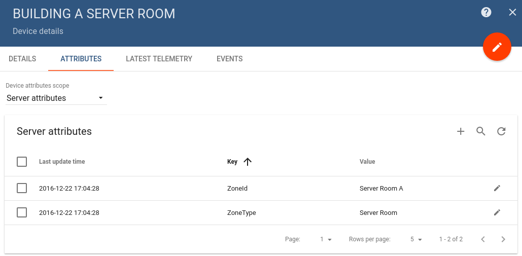
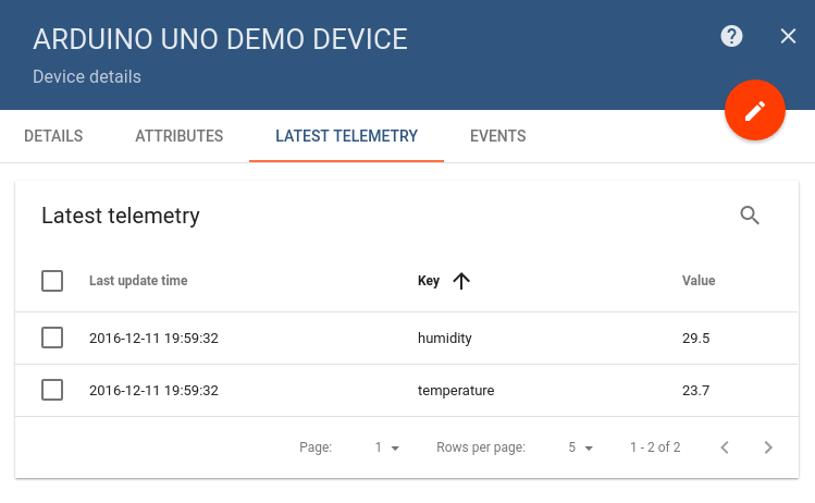
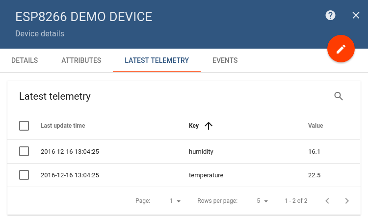
Go to “Devices” section and locate “ESP8266 Demo Device”, open device details and switch to “Latest telemetry” tab.
If all is configured correctly you should be able to see latest values of “temperature” and “humidity” in the table.
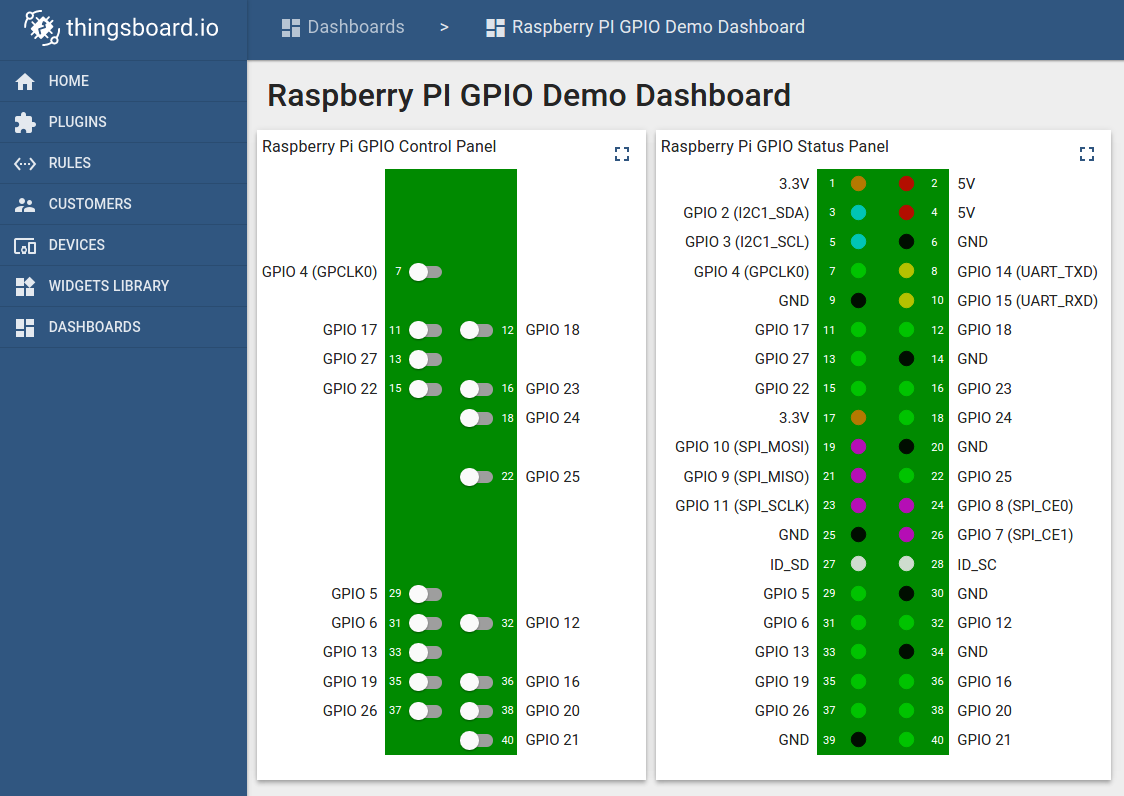
After, open “Dashboards” section then locate and open “ESP8266 DHT22: Temperature & Humidity Demo Dashboard”.
As a result you will see two digital gauges and two time-series charts displaying temperature and humidity level (similar to dashboard image in the introduction).
Next steps
Browse other samples or explore guides related to main Thingsboard features: