Thingsboard is an open-source server-side platform that allows you to monitor and control IoT devices. It is free for both personal and commercial usage and you can deploy it anywhere. If this is your first experience with the platform we recommend to review what-is-thingsboard page and getting-started guide.
This sample application will allow you to control GPIO of your ESP8266 device using Thingsboard web UI. We will observe GPIO control using Leds connected to the pins. The purpose of this application is to demonstrate Thingsboard RPC capabilities.
The application that is running on ESP8266 is written using Arduino SDK which is quite simple and easy to understand. ESP8266 offers a complete and self-contained Wi-Fi networking solution. ESP8266 push data to Thingsboard server via MQTT protocol by using PubSubClient library for Arduino. Current GPIO state and GPIO control widget is visualized using built-in customizable dashboard.
The video below demonstrates the final result of this tutorial.
Prerequisites
You will need to Thingsboard server up and running. Use either Live Demo or Installation Guide to install Thingsboard.
List of hardware and pinouts
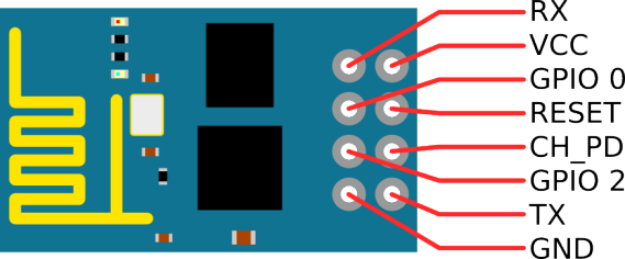
-
USB to TTL
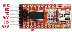
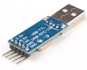
-
Breadboard
-
2 female-to-female jumper wires
-
7 female-to-male jumper wires
-
2 Leds
-
3.3V power source (for example 2 AA batteries)
Wiring schemes
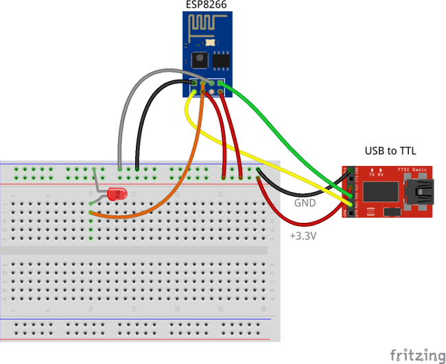
Programming/flashing schema
| ESP8266 Pin | USB-TTL Pin |
|---|---|
| ESP8266 VCC | USB-TTL VCC +3.3V |
| ESP8266 CH_PD | USB-TTL VCC +3.3V |
| ESP8266 GND (-) | USB-TTL GND |
| ESP8266 GPIO 0 | USB-TTL GND |
| ESP8266 RX | USB-TTL TX |
| ESP8266 TX | USB-TTL RX |
| LED 1 Pin | USB-TTL Pin |
|---|---|
| cathode | USB-TTL GND |
| LED 1 Pin | ESP8266 Pin |
|---|---|
| anode | ESP8266 GPIO 2 |
The following picture summarizes the connections for this project in programming/debug mode:
Final schema (Battery Powered)
| ESP8266 Pin | 3.3V power source |
|---|---|
| ESP8266 VCC | VCC+ |
| ESP8266 CH_PD | VCC+ |
| ESP8266 GND (-) | VCC- |
| LED 1 Pin | ESP8266 Pin |
|---|---|
| anode | ESP8266 GPIO 2 |
| LED 1 Pin | 3.3V power source |
|---|---|
| cathode | VCC- |
| LED 2 Pin | ESP8266 Pin |
|---|---|
| anode | ESP8266 GPIO 0 |
| LED 2 Pin | 3.3V power source |
|---|---|
| cathode | VCC- |
The final picture:

Thingsboard configuration
Note Thingsboard configuration steps are necessary only in case of local Thingsboard installation. If you are using Live Demo instance all entities are pre-configured for your demo account. However, we recommend to review this steps because you will still need to get device access token to send requests to Thingsboard.
Provision your device
This step contains instructions that are necessary to connect your device to Thingsboard.
Open Thingsboard Web UI (http://localhost:8080) in browser and login as tenant administrator
- login: [email protected]
- password: tenant
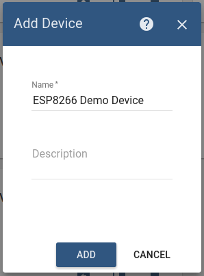
Goto “Devices” section. Click “+” button and create device with name “ESP8266 Demo Device”.
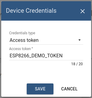
Once device created, open its details and click “Manage credentials”. Copy auto-generated access token from the “Access token” field. Please save this device token. It will be referred to later as $ACCESS_TOKEN.
Click “Copy Device ID” in device details to copy your device id to clipboard. Paste your device id to some place, this value will be used in further steps.
Provision your dashboard
This step contains instructions that are necessary to provision new dashboard with map widgets to Thingsboard.
Open “Terminal” and download file containing demo dashboard JSON:
curl -L https://thingsboard.io/docs/samples/esp8266/resources/esp8266_gpio_dashboard.json > esp8266_gpio_dashboard.json
Update dashboard configuration with your device Id (obtained in previous step) by issuing the following command:
sed -i "s/{DEVICE_ID}/<your device id>/" esp8266_gpio_dashboard.json
Obtain JWT token by issuing login POST command:
curl -X POST --header 'Content-Type: application/json' --header 'Accept: application/json' -d '{"username":"[email protected]", "password":"tenant"}' 'http://localhost:8080/api/auth/login'
You will receive response in the following format:
{"token":"$YOUR_JSON_TOKEN", "refreshToken": "$REFRESH_TOKEN"}
copy $YOUR_JSON_TOKEN to some place. Note that it will be valid for 15 minutes by default.
Execute dashboard upload command:
curl -X POST --header 'Content-Type: application/json' --header 'Accept: application/json' --header 'X-Authorization: Bearer $YOUR_JSON_TOKEN' -d "@esp8266_gpio_dashboard.json" 'http://localhost:8080/api/dashboard'
Programming the ESP8266
Step 1. ESP8266 and Arduino IDE setup.
In order to start programming ESP8266 device you will need Arduino IDE installed and all related software.
Download and install Arduino IDE.
After starting arduino, open from the ‘file’ menu the preferences.
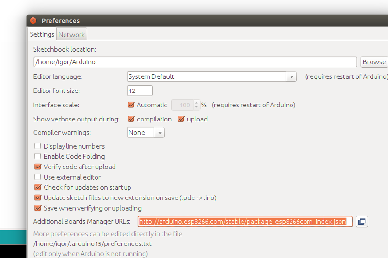
Fill in the “Additional board managers URL” this url: http://arduino.esp8266.com/stable/package_esp8266com_index.json
Close the screen by the OK button.
Now we can add the board ESP8266 using the board manager.
Click in the menu tools the menu option Board: “Most likely Arduino UNO”. There you will find the first option “Board Manager”.
Type in the search bar the 3 letters ESP. Locate and click on “esp8266 by ESP8266 Community”. Click on install and wait for a minute to download the board.
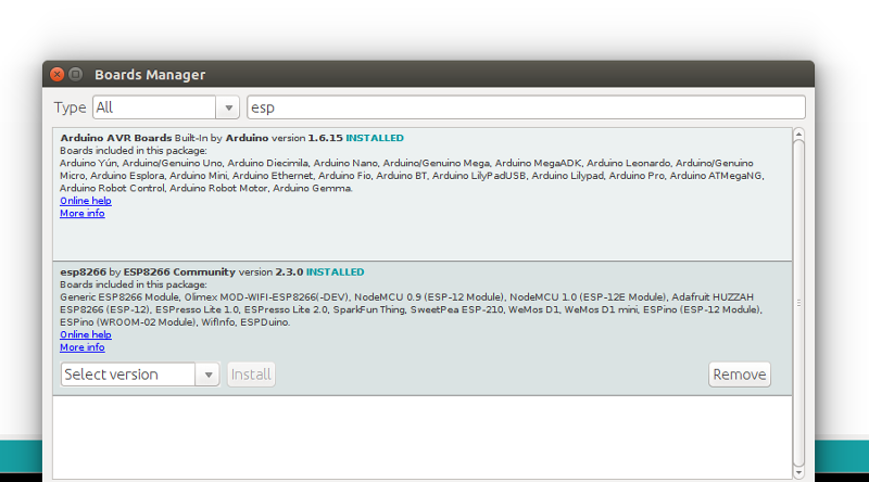
Note that this tutorial was tested with the “esp8266 by ESP8266 Community” version 2.3.0.
In the menu Tools “Board “Most likely Arduino UNO” three new boards are added.
Select “Generic ESP8266 Module”.
Prepare your hardware according to the Programming/flashing schema. Connect USB-TTL adapter with PC.
Select in the menu Tools, port the corresponding port of the USB-TTL adapter. Open the serial monitor (by pressing CTRL-Shift-M or from the menu Tools). Set the key emulation to “Both NL & CR” and the speed to 115200 baud. This can be set in the bottom of terminal screen.
Step 2. Install Arduino libraries.
Open Arduino IDE and go to Sketch -> Include Library -> Manage Libraries. Find and install the following libraries:
Note that this tutorial was tested with the following versions of the libraries:
- PubSubClient 2.6
- ArduinoJson 5.8.0
Step 3. Prepare and upload sketch.
Download and open esp8266-gpio-control.ino sketch.
Note You need to edit following constants and variables in the sketch:
- WIFI_AP - name of your access point
- WIFI_PASSWORD - access point password
- TOKEN - the $ACCESS_TOKEN from Thingsboard configuration step.
- thingsboardServer - Thingsboard HOST/IP address that is accessable within your wifi network. Specify “demo.thingsboard.io” if you are using live demo server.
resources/esp8266-gpio-control.ino |
|---|
|
Connect USB-TTL adapter to PC and select the corresponding port in Arduino IDE. Compile and Upload your sketch to device using “Upload” button.
After application will be uploaded and started it will try to connect to Thingsboard node using mqtt client and upload current GPIOs state.
Autonomous operation
When you have uploaded the sketch, you may remove all the wires required for uploading including USB-TTL adapter and connect your ESP8266 and LEDs directly to power source according to the Final wiring schema.
Troubleshooting
In order to perform troubleshooting you should assemble your hardware according to the Programming/flashing schema. Then connect USB-TTL adapter with PC and select port of the USB-TTL adapter in Arduino IDE. Finally open “Serial Monitor” in order to view debug information produced by serial output.
Data visualization
Finally, open Thingsboard Web UI. You can access this dashboard by logging in as a tenant administrator.
In case of local installation:
- login: [email protected]
- password: tenant
In case of live-demo server:
- login: your live-demo username (email)
- password: your live-demo password
See live-demo page for more details how to get your account.
Once logged in, open Dashboards->ESP8266 GPIO Demo Dashboard page. You should observe demo dashboard with GPIO control and status panel for your device. Now you can switch status of GPIOs using control panel. As a result you will see LEDs status change on device and on the status panel.
Below is the screenshot of the “ESP8266 GPIO Demo Dashboard”.

Next steps
Browse other samples or explore guides related to main Thingsboard features:
- Device attributes - how to use device attributes.
- Telemetry data collection - how to collect telemetry data.
- Using RPC capabilities - how to send commands to/from devices.
- Rule Engine - how to use rule engine to analyze data from devices.
- Data Visualization - how to visualize collected data.
Can you show us how to do it using an Arduino? Thank you a lot!
ReplyDeleteCode is not compiling
ReplyDeletecurl -X POST --header 'Content-Type: application/json' --header 'Accept: application/json' --header 'X-Authorization: Bearer $YOUR_JSON_TOKEN' -d "@esp8266_gpio_dashboard.json" 'http://localhost:8080/api/dashboard'
ReplyDeleteGetting Error After applying above command :
{"status":401,"message":"Invalid username or password","errorCode":10,"timestamp":1550819762513}
Connecting to ThingsBoard node ...[FAILED] [ rc = -2 : retrying in 5 seconds]
ReplyDeleteWhat a fantabulous post this has been. Never seen this kind of useful post. I am grateful to you and expect more number of posts like these. Thank you very much. centralina aggiuntiva opel
ReplyDeletespam ......
DeleteThingsboard Web UI (http://localhost:8080)
Deletehow to reach that
does terminal mean cmd in window
DeleteVery informative post! There is a lot of information here that can help any business get started with a successful social networking campaign. spy phone app
ReplyDeleteNice Blog. Thanks for sharing with us. Such amazing information.
ReplyDeleteOnly Blog
Guest Blogger
Guest Blogging Site
Guest Blogging Website
Guest Posting Site
I visit toiphone Store and here someone told me about thingsboard. Thingsboard is an open source platform that allows you to monitor and control IoT devices. It is free for both personal and commercial usage.
ReplyDeleteIt will reduce stress very effectively vampire survivors. Have a nice day
ReplyDeleteXiaomi phones in Canada are game-changers! With their cutting-edge features, sleek design, and affordable prices, they're taking the smartphone market by storm. I'm loving the Xiaomi experience, and it's great to see more options in the Canadian market!
ReplyDeleteThingsboard unlocks the potential of GPIO control via MQTT! Dive into the realm of seamless connection between your devices and the Thingsboard platform, guided by Solo Lisa through the complexities of managing General Purpose Input/Output. With this meta description, you can enhance your IoT experience and have access to efficient, real-time control!Thank you for sharing your knowledge! Keep up the good job! Continue to spread the word. Please take a peek at my website.
ReplyDeletetruck accident attorney near me
Efficiently manage ESP8266 GPIO pins through MQTT integration with Thingsboard, enabling seamless communication and control for IoT applications.Lawyers in new york||Lawyers in new jersey Harness the power of ESP8266 to manipulate GPIO states effortlessly via MQTT, seamlessly connecting with Thingsboard for streamlined monitoring and control in IoT environments.
ReplyDelete
ReplyDeleteControlling GPIO pins on an ESP8266 device using MQTT (Message Queuing Telemetry Transport) via Thingsboard minecraftle involves several steps.
Tastings at breweries are like gourmet adventures where you get to sample a variety of wonderful tiger exchange or beers. It's an enjoyable opportunity to sample new cuisines and socialize with like-minded individuals. Toast to tastings at breweries!
ReplyDeleteI'm learning so much from moonshine mountain your blog, thank you for sharing your expertise!
ReplyDeletenclude the necessary libraries for MQTT communication Watermelon Game and GPIO control. Libraries like PubSubClient for MQTT and Arduino core for ESP8266 can be used.
ReplyDeleteflavoring syrups is a versatile and delectable addition to any kitchen pantry. Known for its rich, buttery flavor and smooth texture, it enhances a variety of dishes from desserts like ice cream and pancakes to beverages such as coffee and cocktails.
ReplyDeleteDiscover the ultimate gift of luxury with our curated selection of online perfume
ReplyDelete. Ideal for any special occasion, our sets feature a variety of exquisite fragrances from top brands,
For projects in medical cloud saudi , consider using local cloud services that comply with Saudi data protection regulations. This ensures that your medical data is stored and handled according to regional requirements.
ReplyDeleteI’ve shared this post south pole clothing with my friends. Great work!
ReplyDeleteDrive Mad has quickly gained popularity because it delivers a unique balance of fun and frustration. The physics-based mechanics make each playthrough unpredictable, giving the game high replayability.
ReplyDelete"Fantastic tutorial on GPIO control over MQTT! 📡🔌 The step-by-step breakdown made it so easy to follow along. I love how you demonstrated the real-time control capabilities—it's a game changer for IoT projects! Can't wait to implement this in my own setups. Thanks for sharing your expertise! #IoT #MQTT #GPIOControl"
ReplyDeletevirginia class action lawsuit
Pyramixed is a popular music game to Pyramixed - Sprunki Pyramixed stands as the latest enchanting addition to the musical world, bringing a magical rhythmic experience that sets a new standard for interactive entertainment.
ReplyDeleteCreating music in Sprunki Scrunkly is refreshingly simple yet endlessly engaging. The Sprunki Scrunkly interface lets you drag and drop characters onto your stage, and watch as they blend their unique loops and sounds into harmonious arrangements. From upbeat melodies to groovy rhythms, every element works together to create something special.Scrunkly - your gateway to musical creativity! Sprunki Scrunkly is a delightful fan-made mod for Incredibox that transforms music creation into a whimsical adventure.
ReplyDeleteai music generator
ReplyDeletesprunki 1996
Love Pawsona
ReplyDeleteCool tutorial! I've been looking [for a simple](https://personalhealthcart.com) way to control my ESP8266 with Thingsboard. This seems pretty straightforward and well-documented. I'm definitely going to give it a try this weekend!
ReplyDeleteThis looks like a really cool project! I've been wanting to play around with Thingsboard and ESP8266 for a while. The step-by-step guide seems pretty clear, I might actually give this a try this weekend.
ReplyDeleteThis looks like a pretty cool tutorial! I've been meaning to try out Thingsboard with my ESP8266. The step-by-step instructions seem easy to follow, hopefully I can get it working without [too much](https://bamboo-fiber-clothing.com) trouble.
ReplyDeleteCool IoT project! While working on creative tech stuff, I sometimes take breaks to play with the Ghibli AI Generator. It's fun seeing photos turn into magical Ghibli-style art. Might make a cool animated dashboard background for Thingsboard too!
ReplyDeleteThe application that is running on ESP8266 is written using Arduino SDK which is quite simple and easy to understand.abgerny game
ReplyDeleteGreat article on ESP8266 GPIO control! I’ve been exploring IoT projects and this setup looks super useful. By the way, if you’re into hands-on learning, a suture kit from Pinnacle Medics is a great way to practice precision—just like tweaking those GPIO pins! Keep up the awesome work.
ReplyDelete